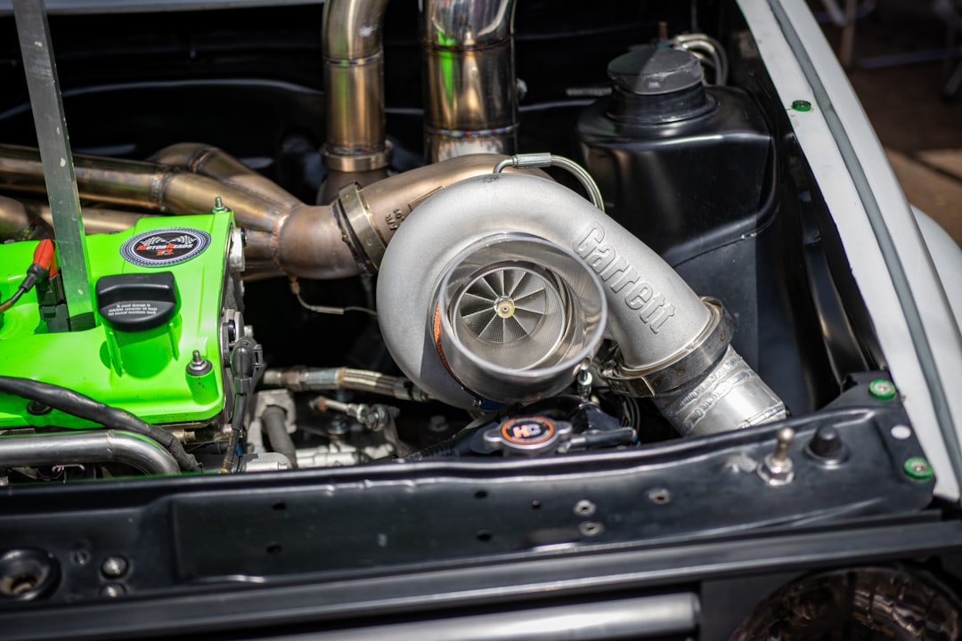

The G Series II family includes several frame sizes, including the G25, G30, G35, G42, G45, and G55. That range allows a builder to work from the engine’s airflow requirement instead of treating one model as a universal answer. A modest street four-cylinder, a larger six-cylinder, and a competition engine that spends long periods at high rpm may need very different compressor and turbine combinations. Before ordering, record the chosen frame, compressor specification, turbine housing, flange pattern, outlet style, and any available center housing options. The family name alone does not confirm a direct installation.
Compressor maps provide a useful check against optimistic power targets. They relate pressure ratio and airflow to efficiency zones and surge or choke limits. Pressure ratio is based on absolute pressure at the compressor outlet compared with pressure at its inlet, while airflow reflects the engine’s demand at a particular speed and load. The map does not replace a full engine model, but it can show whether the expected operating points sit in a practical area. A turbo selected only for its peak flow may spend ordinary street driving below its most responsive range. Reviewing the map across the whole rpm band is more informative than examining one dyno target.
Turbine sizing changes the result just as much as compressor selection. The housing A/R value describes the relationship between the passage area and its radius from the turbine wheel. A smaller value often increases gas velocity and can improve response, while a larger value may provide more flow capacity at elevated engine speed. Those tendencies depend on displacement, exhaust energy, cam timing, manifold volume, and backpressure, so they should not be treated as fixed rules. Two turbos with similar compressor specifications can behave very differently if their turbine wheels or housings differ. Compare the complete turbine specification, not just the compressor inducer or advertised power range.
Physical clearance deserves a measurement sheet of its own. Confirm the exhaust flange and manifold position, compressor inlet diameter, outlet orientation, oil feed thread, drain location, and coolant connections where applicable. Measure from the turbo centerline to the radiator, strut tower, hood, intake pipe, and nearby heat-sensitive components. A useful workshop habit is to print the installation drawing and mark each connection before fabrication begins. The oil drain should fall continuously toward the crankcase without a sharp rise, and the feed should be clean and correctly sized. A turbo can be well matched for airflow and still fail as an installation if the plumbing, access, or service clearance is poor.
Wastegate selection and boost control need their own review. The wastegate diverts part of the exhaust stream around the turbine so the control system can regulate boost. An internal gate may simplify a compact manifold, while an external gate can suit a manifold designed with a separate bypass path. The important questions include actuator reference routing, valve sizing, exhaust discharge, boost controller placement, and engine management strategy. A pressure line connected to the wrong source can produce inconsistent control, and exhaust plumbing that obstructs the gate outlet can undermine the intended setup. Boost creep is a control and flow problem, not proof that the turbo is merely making extra useful power. For additional turbo fitment reference, compare the required connections with the actual parts list rather than relying on a product title.
The best choice also depends on how the vehicle is used. A small-displacement manual street car that spends much of its time below the upper third of the tachometer may benefit from early torque and a broad usable range. A larger turbo could reach the desired peak output, yet demand more engine speed and exhaust flow before it becomes effective. A track car with greater displacement, aggressive cams, and sustained high rpm may support a larger frame more naturally. Before selecting hardware, write down the target power, fuel type, redline, usual shift points, transmission, tire use, and expected boost range. That simple record often exposes a mismatch between a headline power goal and the way the car is actually driven.
Installation is only the midpoint of the job. Verify injector and pump capacity, sensor ranges, fuel pressure behavior, intercooler routing, and the engine management settings before applying full load. Use conservative initial calibration, pressure-test the intake system, inspect oil and coolant joints, and confirm that the wastegate actuator moves as intended. During controlled testing, monitor boost, air-fuel ratio, charge temperature, exhaust temperature where available, and signs of oil carryover. Keep the final hardware list and calibration notes with the vehicle record so later changes can be traced. The turbo works as intended only when its compressor, turbine, manifold, controls, lubrication, cooling, fuel delivery, and tune operate as one matched package.